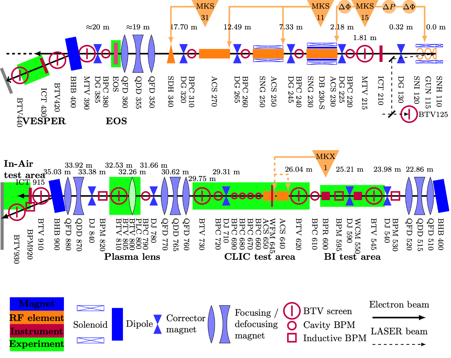
The CERN Linear Electron Accelerator for Research (CLEAR) is an accelerator running R&D for the future CLIC machine. CLEAR is a LINAC beamline that can accelerate electrons up to very high energies (55-220 MeV). There are currently two test stations capable of hosting radiation effects on electronics studies. The first is the Very energetic Electron facility for Space Planetary Exploration missions in harsh Radiative environments (VESPER). The second is the TeraHertz (THz) test station. Both test stations make use of the same LINAC structure to accelerate electrons and they are in the same irradiation hall, just on separate beamlines.

The electrons can either be generated using the dark current of the electron gun (in this case the electron flux is rather low) or by excitation through a laser (in this case the electron flux may become very high). The accelerating structure is based on two klystrons (which are shown on the top part of Figure 1) and three consecutive Accelerating Structures (ACS) that can impart an acceleration to the electron beam. Currently, it is not possible to accelerate electrons at energies below 55 MeV since this is the minimum energy imparted by the first ACS. When energies in the order of 60 MeV are needed, only the first ACS is used. The other ACSs are used when the energy has to be increased from 65 to 220 MeV. A triplet of quadrupoles can be used to focus the electron beam just before the dipole magnet, which brings the beam to the VESPER test station. The THz test station is located another 15 meters downstream the main beamline. The beam passes through several additional quadrupole triplets before getting to the THz test station.
The beam is accelerated in bunches with a very short length (0.5-10 ps) that can be selected by the user, but such adjustments require changing the tuning of the klystrons. Bunches are repeated with a frequency of 3 GHz, corresponding to a bunch separation of 333 ps. During the acceleration phase the bunches have mainly a longitudinal extension.
The charge (number of electrons) in each bunch can be selected. Usually, the user has first to select a certain train charge and then derive the charge per bunch by the number of bunches contained in a train. The train is indeed a series of consecutive bunches repeated at a 3 GHz frequency. The train charge can be spread over 1 to 180 bunches. However, this cannot be achieved for any train charge. It is not possible to have 180 bunches with relatively low train charge (100 pC) as well as it is not possible to have 1 bunch with very high train charge (10 nC).
The train is nominally repeated every 1.2 seconds (0.8 Hz). However, in order to increase the average flux, it is possible to request several repetition rates between 0.8 and 10 Hz. The logging of the beam parameters is nominally performed only each 1.2 seconds even when the repetition rate is increased. If, for instance, a 10 Hz repetition rate is used, the logged charge has to be multiplied by a factor 12 to retrieve the actual electron fluency delivered to the DUT.
When generating the beam with the dark current of the gun the maximum train charge that can be achieved at the VESPER station is about 15 pC. When using the laser to generate the beam the minimum train charge that can be achieved at VESPER is about 30 pC and the maximum is about 10 nC. The THz station is only used for high-intensity beams and it allows achieving train charges as high as 30 nC. The limitation at VESPER is due to the energy spread sensitivity that may cause a spread in the beam field size if the intensity is raised above 10 nC.
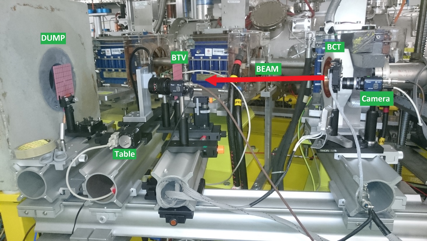
The facility logging system reports data related to the beam intensity and the beam profile (FWHM). Irradiations at both VESPER and THz are performed in air with the electron travelling through air for about 1 meter before reaching the DUT. No strong influence from air interaction is expected. The beam current is measured by a Beam Current Transformer (BCT) positioned just 30 cm ahead of the DUT position. The BCT provides the charge measured in each train (but only every 1.2 seconds). A BTV YAG screen coupled with a camera is used to retrieve the beam shape and calculate the FWHM. This is sampled and logged every 1.2 seconds, too. The VESPER test station is shown in Figure 2 along with many of its instruments. The FWHM of the beam is usually restricted to something between 5 and 15 mm diameter, which is enough to irradiate homogeneously one die of the ESA Monitor.
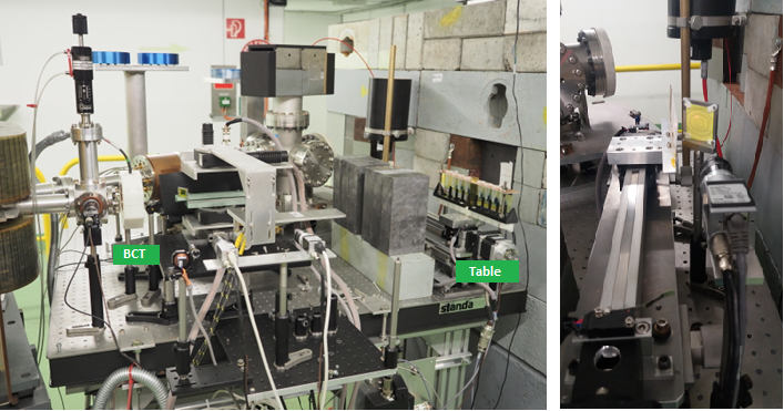
The DUTs have to be mounted on the table shown in Figure 2. Usually, this is achieved by a plexiglass or metal plate which is fixed at the table and on which it is possible to drill holes to install the DUTs/boards. The standard table used by the facility allows remote alignment only in the horizontal direction, but not in the vertical. The DUTs have to be mounted so that the sensitive part is at the same height for all of them. The alignment of each DUT in the horizontal direction is performed through a laser system. A camera system is available, but the alignment has to be completed during the installation. Several tables are available and the longest range available is 30 cm. Figure 3 shows the THz test station.

The facility only has simple electrical connections towards the barrack positioned outside the irradiation hall. A maximum of 2 BNC and 2 Ethernet connections are currently pulled and available to the user. The total length of such cables is about 20 meters. 1-2 meter cables are necessary to reach from the DUT to the existing connectors. Additional cables can be pulled through a hole between the barrack and the irradiation hall. 20 meters may suffice to get to the DUT at VESPER. For THz, 30 meters minimum are required. In some cases, it is possible to leave some equipment inside the irradiation hall. The electron beam is very well focused and the stray field (mainly composed of photons and photo-neutrons) is very weak. However, it is usually good practice to shield the equipment with lead bricks available at the facility. In addition, the equipment left inside will have to be cleared by radiation protection. The DUT itself will typically not be cleared by radiation protection as non-radioactive, and will, therefore, require a certain cooling time and/or further analysis (e.g. gamma spectroscopy).

More information are available at https://clear.cern/ and http://vesper.web.cern.ch/ .
