The CERN Highly-Accelerated Mixed Field Facility (CHARM) at CERN is a facility for testing radiation effects on electronics like no others. The proton beam is obtained in spills with an intensity of approximately 5×10¹¹ protons and a duration of around 350 ms from the Proton Synchrotron (PS) of the CERN accelerator complex and has a momentum of 24 GeV/c. The spill is repeated around three times during a super-cycle of 45 seconds.
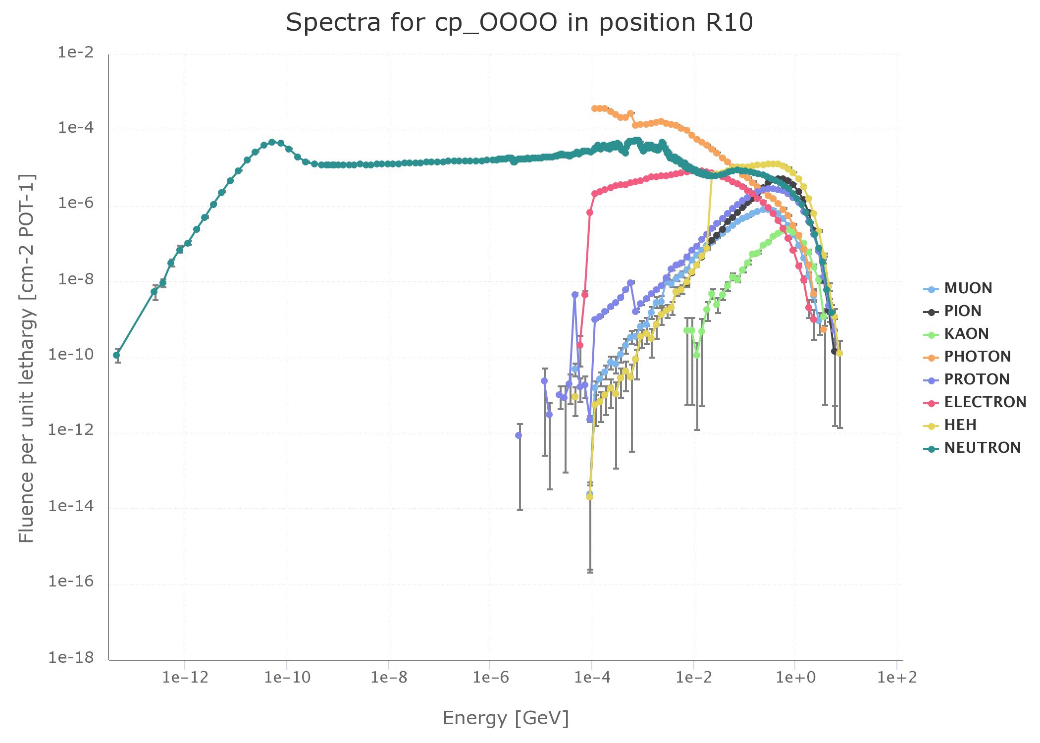
The primary proton beam impinges on a metal target inside the irradiation room. Three targets are available: copper, aluminum and aluminum with holes, in order to produce various mixed-field intensities. The target extends for 50 cm in the beam longitudinal direction, and has a diameter of 8 cm. The proton beam interacts with the target atoms leading to nuclear spallation reactions, which unleash a large amount of particle species over a wide range of energy spectrum, thus the mixed-field (see Figure 1 for an example of the particle spectra). Electronics in the irradiation room will mainly interact with protons, neutrons, electrons, pions, photons, muons and kaons ranging from thermal energies (for neutrons) up to some GeV. A further variation in beam intensity can be obtained by inserting a movable shielding. This is made of four concrete and iron walls, each 20 cm thick, that can be inserted in-between the target and the lateral testing positions. Standard configuration has no shielding. Half-shielding configuration is obtained by inserting one concrete and one iron wall. Full-shielding is obtained by inserting the remaining two walls. The shielding reduces the mixed field intensity and spectra hardness. It also affects the beam composition, above all, by increasing neutron abundancy. Usually, the CHARM configuration is expressed by an acronym indicating the target material (Cu, Al, AlH, NT) and the shielding (OOOO, CIOO, CIIC).

Given the composition variability of the mixed field, it is impossible to distinguish fluxes of single particles, if not by means of Monte-Carlo simulations. Best practice is to indicate some other quantities for defining the flux intensity. The High Energy Hadron (HEH) flux is the flux of all hadrons (protons, neutrons, pions, etc.) having an energy above 20 MeV. Those are the particles that can interact with electronics through nuclear reaction. The HEH flux can be employed as a reference for determining beforehand the expected level of SEEs, if cross-section data obtained at other facilities are available. Synergistic effects, e.g. TID and DDD, are also present. At CHARM, on average, 109 HEH/cm2 approximately deposits 1 Gy(Si) and 1 HEH/cm2 corresponds to roughly 4 neq/cm2 (1 MeV neutrons equivalent flux, used as a measure for DDD).
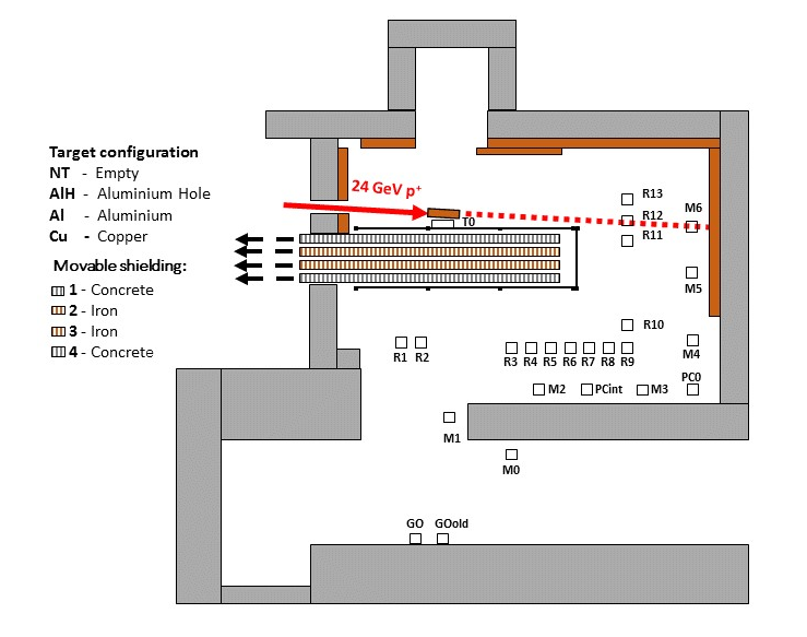
Another important characteristic is that the electronics is not installed at a specified place, but it can be tested potentially everywhere inside the irradiation areas in Figure 2. Thus, the radiation environment composition and spectrum vary according to the distance and angular deviation from the target. Generally, the facility provides some standard test positions (see Figure 2). The RX positions are the most used. R5 is typically used for reproducing the space environment conditions, R10 and R13 for accelerator as well as ground and atmospheric environment (with some orders of magnitude difference in the accelerator factor). Positions like R12 are rarely used due to huge gradients and beam non-uniformity. The RX positions require the electronics to be rackable, i.e. mounted on a standard 19” rack by means of epoxy, Plexiglas or aluminum plates. Other, less standard, positions may be used as an alternative for certain experiments. A first option is to exploit some movable structures, e.g. the Montrac and the overhead conveyer to position a smaller rack all along the wall in position defined as MX and PCX. The flexibility is given by the fact that the rack can theoretically be positioned continuously all along the path from M0 to M6. Finally, the G0 position is the farthest from the target and has the lowest flux.

Testing at CHARM comes with some important constraints that may have an impact on preparing the test setup.
- As previously introduced, the mixed-field beam can reach up to any corner of the irradiation room. That means that each electronic element positioned in the irradiation room will be irradiated and might suffer from radiation issues. Owing to the very high energies involved, local shielding to protect readout electronics is not an option. Therefore, this requires some specific consideration when setting up a test at CHARM, as introducing a tester in the irradiation room may lead to unwanted radiation issues.
- Irradiation runs at CHARM have fixed duration. Accesses are regulated by radiation protection and are authorized only every 7 days, typically on Wednesday morning. No accesses are possible from Wednesday at noon until the next Wednesday, hence it is not possible to update the setup during the week or to recover faulty elements before a new access is granted. This procedure is due to the large level of activation inside the irradiation room. Only limited time access is possible and, after the irradiation run, the irradiated electronic equipment cannot be recovered immediately for measurements, but it has to cool down for some time in the internal buffer zone. Afterwards, the electronic components will be considered as radioactive material from CERN and will in general not be declassified. They can only be sent to institutions capable of handling radioactive material.
- The target is inserted in the beam for 5 days, from Wednesday afternoon to Monday afternoon. It is then removed and confined behind a marble door until the next Wednesday. The beam is still delivered to CHARM between Monday and Wednesday. However, it is a pure proton beam that just goes through the irradiation room and hits the dump. A weak radiation field may also be observed for very sensitive measurement elements.
- Pulling cables is usually not allowed at CHARM. The patch panel already provide plenty of cables connectors. A full list can be found at http://charm.web.cern.ch/content/cables-and-networking . The internal patch panel is located in the bottom left corner in Figure 2. The distance between this internal patch panel and that in the control room is 17 meters. All the cables connected to electronics in any position (except the overhead conveyer) are pulled from the internal patch panel to the rack inside cable chains. These are prepared in advance and positioned during the transportation of the rack towards the final position by means of a robot. The user is requested to provide the cables for the control room and for the irradiation area. Cables in the control room may account for 3 meters maximum length. The cable length for the irradiation room varies accordingly to the position. 5 meters can be accounted for G0, around 15 meters for R10 and 18 for R13. The overhead conveyer is the only exception. The cables are already pulled inside the chain for a length of around 15 meters. Cables going into the irradiation room cannot be recovered and have to observe a period of cooling after irradiation. They can nonetheless be reused at CHARM in future irradiation runs.
- Target, shielding and test positions are not usually freely chosen by the user. They are usually defined according to the main user of the facility during the irradiation week. In spite of the large number of positions available in Figure 2, only one rack can be introduced in the internal irradiation room for each irradiation run. The overhead conveyer and position like G0 helps adding flexibility. For experiments not meant to withstand the high fluxes of the internal zone, these are definitely good alternatives. Target and shielding may be changed during the irradiation run upon main user’s request.
- Facility availability is also strictly dependent upon the high energy physics program at CERN, which mainly involves the LHC operations. The CERN accelerator complex (of which PS is part) accelerates protons only between April and October each year, and moves to heavy ions for a limited time in November. Then, the machines are shut down for upgrades until the following March. From time to time, the necessary upgrades are so important that a longer stop is needed (called Long Shutdown).
Dosimetry at the facility is provided by two means. A first pre-irradiation assessment can be performed thanks to FLUKA Monte Carlo simulations (see ‘FLUKA Monte Carlo Modelling of the CHARM Facility’s Test Area: Update of the Radiation Field Assessment’ from A. Infantino at http://cds.cern.ch/record/2291683?ln=en) which have extensively been used for characterizing the mixed field. Among the results, integral quantities and the full particle spectra are provided, allowing to recover the TID, the HEH flux (and thus the expected number of SEE), the 1 MeV neq flux (for DDD), the thermal neutron flux, the hardness factors H50% and H10% (the hardness is used to classify the spectra and to relate it to other radiation environments. H50% provide the HEH energy for which 50% of the particles will lie above in the spectrum. Same applies for H10%.). A useful tool for determining integral quantities and spectra is available at http://charmtoolkit.web.cern.ch.
Dosimetry is available at the facility during irradiation through RadMon measurements. The RadMon is an instrument that allows recovering TID, the HEH flux, the 1 MeV neq flux in real time during irradiation (see ‘A New RadMon version for the LHC and its Injection Lines’ from G. Spiezia et al. at https://ieeexplore.ieee.org/document/6949156). The monitoring tool is available online at http://charm.web.cern.ch/content/charm-tools by downloading the CHARM monitoring tool 2018 java application. RadMon detectors are currently used inside the LHC tunnel for radiation monitoring and characterization purposes.
Website: https://charm.web.cern.ch
